DIN 71752 Form G aus Stahl (G 4 – G 25) mit Feingewinde
Datenblatt
DIN 71752 Form G aus Stahl (G 4 – G 25) mit Feingewinde (FG)
» zum Datenblatt (PDF)Alternative Varianten:
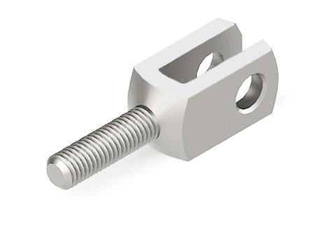
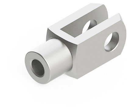
Bestellbeispiel: Gabelköpfe DIN 71752 G 8 x 16 – M 8 FG. Diese entsprechen – bis auf die Kegelkuppe – auch der DIN ISO 8140.
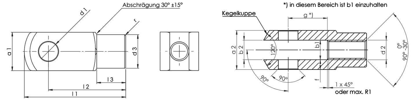
| Bezeichnung Größe |
d1 H9 |
g ±0,5 |
a1 1) |
a2 +0.30 -0.16 |
b1 B13 |
b2 | d2 | d3 ±0,3 |
f ±0,2 |
l1 ±0,5 |
l2 | l3 ±0,2 |
r 2) |
Gewicht ca. kg/Stück |
|
|---|---|---|---|---|---|---|---|---|---|---|---|---|---|---|---|
| Alle Maße bezogen auf die Ermittlung mit gängigen Handmessmitteln. 1) für das Halbzeug gilt die Toleranz h11 nach Din 178 2) Radius oder 45° Fase (nach Wahl) |
|||||||||||||||
| G 4 x 8 FG | 4 | 8 | 8 | 4 | M4 x 0,5 | 8 | 0,5 | 21 | 16 | 6 | 0,5 | 0,005 | |||
| G 4 x 16 FG | 4 | 16 | 8 | 4 | M 4 x 0,5 | 8 | 0,5 | 29 | 24 | 6 | 0,5 | 0,007 | |||
| G 5 x 10 FG | 5 | 10 | 10 | 5 | M 5 x 0,5 | 9 | 0,5 | 26 | 20 | ±0,3 | 7,5 | 0,5 | 0,009 | ||
| G 5 x 20 FG | 5 | 20 | 10 | 5 | B13 | M 5 x 0,5 | 9 | 0,5 | 36 | 30 | 7,5 | 0,5 | 0,013 | ||
| G 6 x 12 FG | 6 | 12 | 12 | 6 | M 6 x 0,75 | 10 | 0,5 | 31 | 24 | 9 | 0,5 | 0,015 | |||
| G 6 x 24 FG | 6 | 24 | 12 | 6 | M 6 x 0,75 | 10 | 0,5 | 43 | 36 | 9 | 0,5 | 0,021 | |||
| G 8 x 16 FG | 8 | 16 | 16 | 8 | M 8 x 1 | 14 | 0,5 | 42 | 32 | 12 | 0,5 | 0,037 | |||
| G 8 x 32 FG | 8 | 32 | 16 | 8 | M 8 x 1 | 14 | 0,5 | 58 | 48 | 12 | 0,5 | 0,054 | |||
| G 10 x 20 FG | 10 | 20 | 20 | 10 | M 10 x 1,25 | 18 | 0,5 | 52 | 40 | 15 | 0,5 | 0,074 | |||
| G 10 x 40 FG | 10 | 40 | 20 | 10 | M 10 x 1,25 | 18 | 0,5 | 72 | 60 | 15 | 0,5 | 0,116 | |||
| G 12 x 24 FG | 12 | 24 | 24 | 12 | M 12 x 1,25 | 20 | 0,5 | 62 | 48 | ±0,4 | 18 | 0,5 | 0,121 | ||
| G 12 x 48 FG | 12 | 48 | 24 | 12 | M 12 x 1,25 | 20 | 0,5 | 86 | 72 | 18 | 0,5 | 0,175 | |||
| G 14 x 28 FG | 14 | 28 | 27 | 14 | M 14 x 1,5 | 24 | 1,0 | 72 | 56 | 22,5 | 1,0 | 0,178 | |||
| G 14 x 56 FG | 14 | 56 | 27 | 14 | +0,7 | M 14 x 1,5 | 24 | 1,0 | 101 | 85 | 22,5 | 1,0 | 0,178 | ||
| G 16 x 32 FG | 16 | 32 | 32 | 16 | +0,15 | M 16 x 1,5 | 26 | 1,0 | 83 | 64 | 24 | 1,0 | 0,282 | ||
| G 16 x 64 FG | 16 | 64 | 32 | 16 | M 16 x 1,5 | 26 | 1,0 | 115 | 96 | 24 | 1,0 | 0,411 | |||
| G 18 x 36 FG | 18 | 36 | 36 | 18 | M 18 x 1,5 | 30 | 1,0 | 94 | 72 | 72 | 1,5 | 0,39 | |||
| G 20 x 40 FG | 20 | 40 | 40 | 20 | M 20 x 1,5 | 34 | 1,0 | 105 | 80 | 30 | 1,5 | 0,55 | |||
| G 20 x 80 FG | 20 | 80 | 40 | 20 | M 20 x 1,5 | 34 | 1,0 | 145 | 120 | 30 | 1,5 | 0,80 | |||
| G 25 x 50 FG | 25 | 50 | 50 | 25 | M 24 x 2,0 | 42 | 1,5 | 132 | 100 | 36 | 1,5 | 1,10 | |||
Werkstoffe: